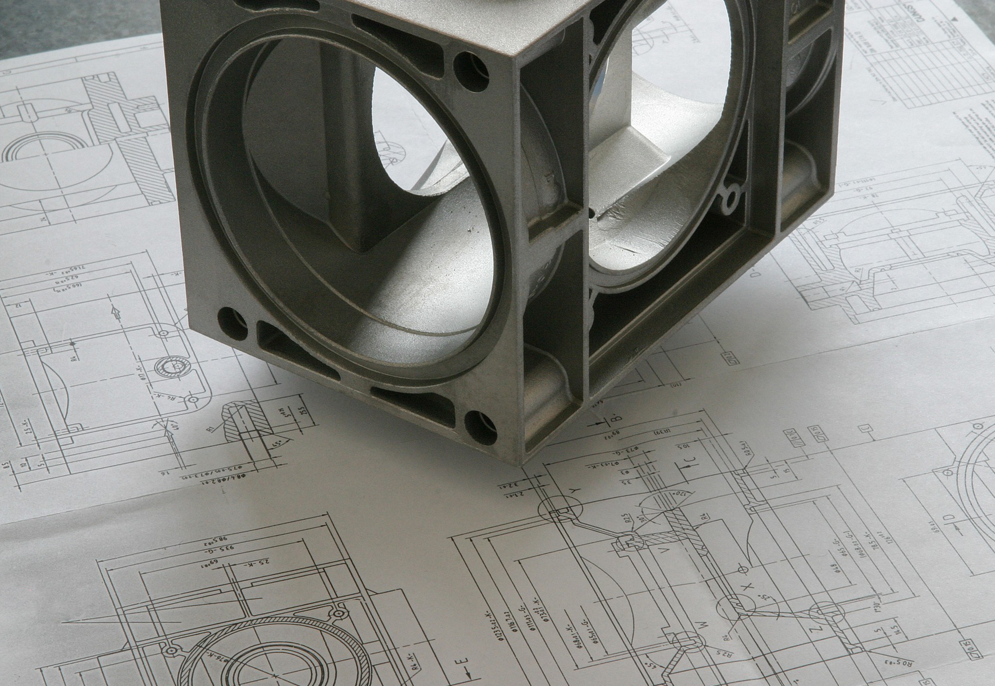
GENERAL TOLERANCES IN THE GPS CONCEPT
2015-06-10 - How do "old" GPS standards agree with current ones?
| Name | Usage | Duration |
|---|---|---|
| privacylayer | Status Agreement Cookie hint | 1 year |
| Name | Usage | Duration |
|---|---|---|
| _ga | Google Analytics | 2 years |
| _gid | Google Analytics | 1 day |
| _gat | Google Analytics | 1 minute |
| _gali | Google Analytics | 30 seconds |

03 March 2014: Gunter Effenberger
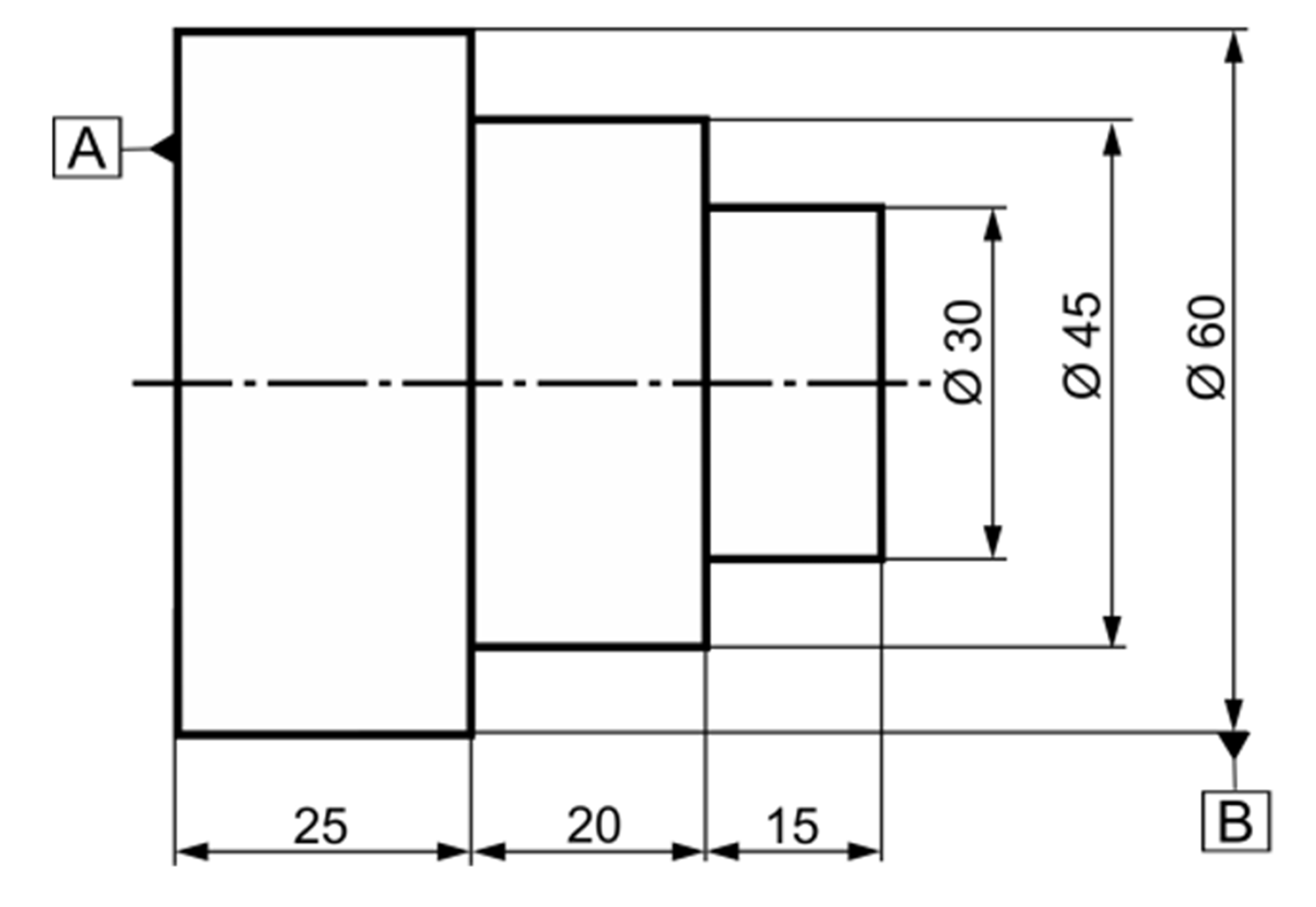
Step dimensions are distances between two opposite planes or edges whose planes / edges are parallel but displaced from one another. You cannot measure the two-point distance based on contact points on the geometric forms and a vertical alignment of one of the two planes / edges (Figure 1). The distances between waves offset from the front surfaces are usually typical step dimensions, too, except for parallel front surfaces restricting annular grooves.
The options available to measure the component in Figure 1 are ambiguous, especially when you apply the two-point size defined on the feature of size.
The ambiguity relating to component inspection is the main reason why ISO 14405-2 suggests replacing linear dimensioning of such step heights by geometrical tolerancing according to ISO 1101.
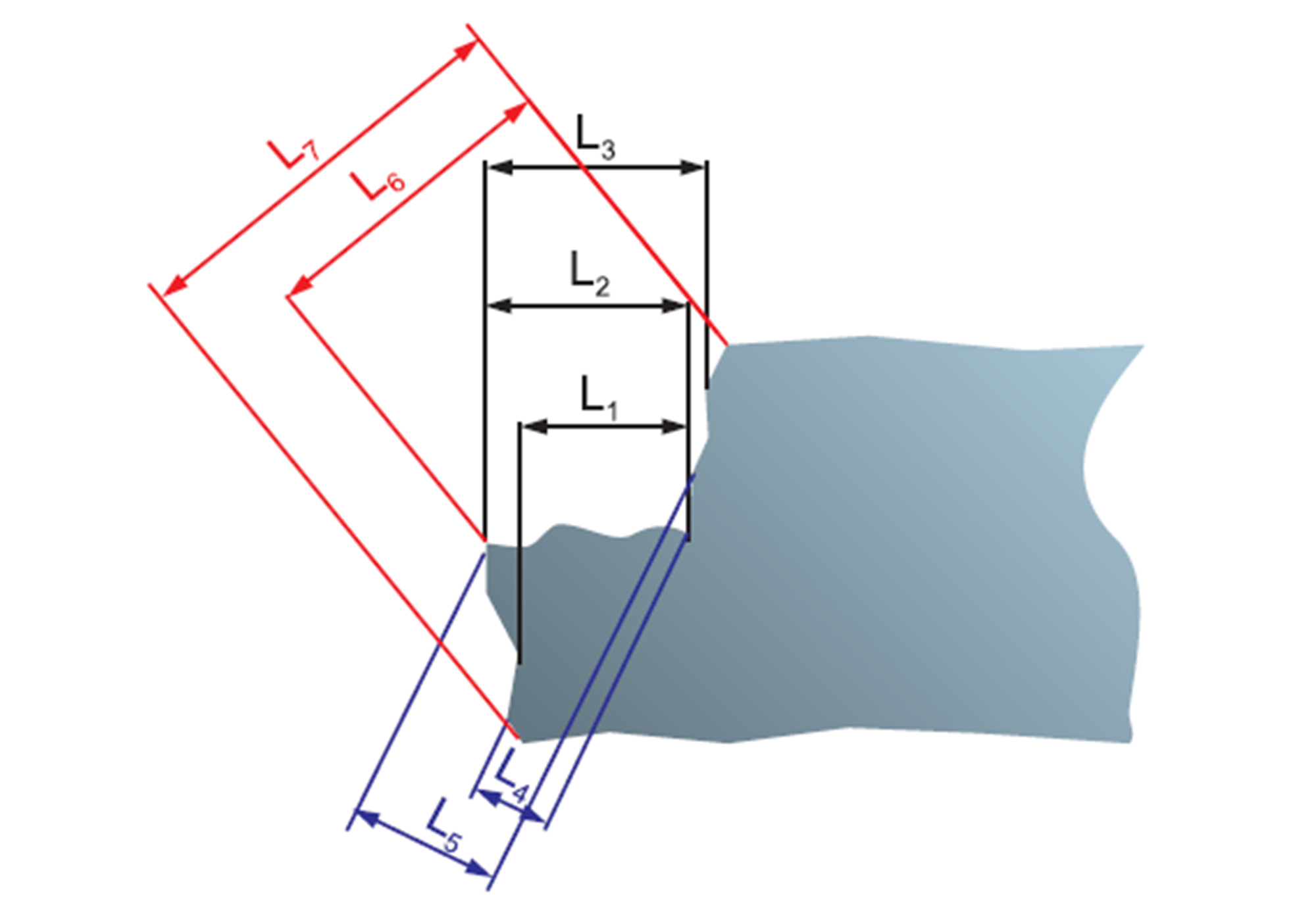
The plane surface as shown in Figure 3 is subject to traditional dimensioning. Even though you might assume that you can dimension this component in a different way to avoid step dimensions – which is absolutely correct – we just ignore this fact right now...